
-
-
Newer Filastruder kits use Socket Cap Head Screws, use them in place of all button head screws in this section unless noted.
-
-
-
THE RAILCORE IS A “DIY” PROJECT - BUILD SAFE, BUILD SMART, AND BE RESPONSIBLE.
-
BUILD AT YOUR OWN RISK.
-
WHEN IN DOUBT, DOUBLE CHECK THINGS.
-
3D PRINTERS CAN GET VERY HOT. USE COMMON SENSE AND QUALITY COMPONENTS.
-
If you need help, find us at the RailCore Facebook page or RailCore Discord channel. Both are linked from RailCore.org
-
-
-
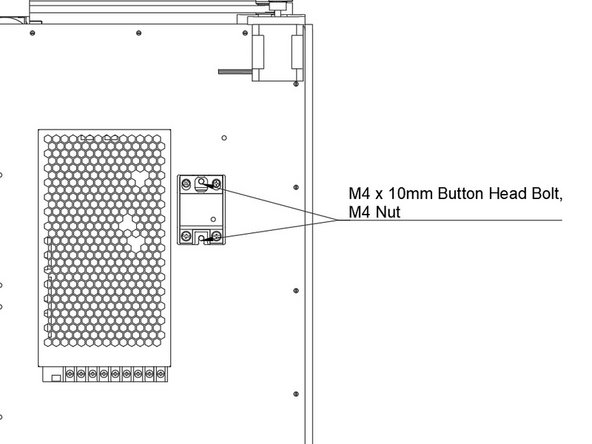
Check the voltage setting on the side of your Power Supply before installing it.
-
Attach the PSU using (4) M4 x 10mm Button Head Bolts. The bolts go through holes in the right panel, and into the back of the PSU.
-
Be sure to install the PSU so the wiring terminals are to the bottom of the printer.
How am I supposed to attach these two parts with 6 4mm x 10mm SHCS when my kit only comes with 5 and there are no button head cap screws in this kit? Why only 5?
Jeff Weiss - Resolved on Release Reply
AGAIN…Remember to check the voltage!! The power brick comes preset at 220V for safety. In the USA nominal voltage is 110 V. When you give power to the printer later on nothing will happen. Make sure you check the voltage before assambly.
Carlos Daniel Stagnaro - Resolved on Release Reply
-
-
-
Install the SSR as shown.
-
Each hole is held in place using (1) M4 x 15mm Socket Cap Head Screws and an M4 nut & Washer
I personally didn't feel comfortable with the SSR sitting on plastic so I purchased two metal standoffs. spacers would work too, to raise it up about 10mm. I'm putting a 40mm x 40mm heat sink with thermal conductive tape to the bottom of the SSR. May be overkill but...
Either way you will probably need to get more or longer screws depending if you use threaded or non-threaded spacers or standoffs.
Make sure the wires are not touching the underside of the SSR or it could melt the plastic around the wire and cause all sorts of problems and it will be dangerous too.
Remember, always be concerned with safety when using Electricity and things that heat like hot ends and heated beds.
Jeffery Seiffert - Resolved on Release Reply
My kit came with 5 M4 x 10mm SCHS screws not 6 and it did have 3 M4 nuts. Please count these fasteners and make the necessary changes to the kits for future customers. Obviously this is an issue. My kit had no M4 button Head screws either.
Jeff Weiss - Resolved on Release Reply
-
-
-
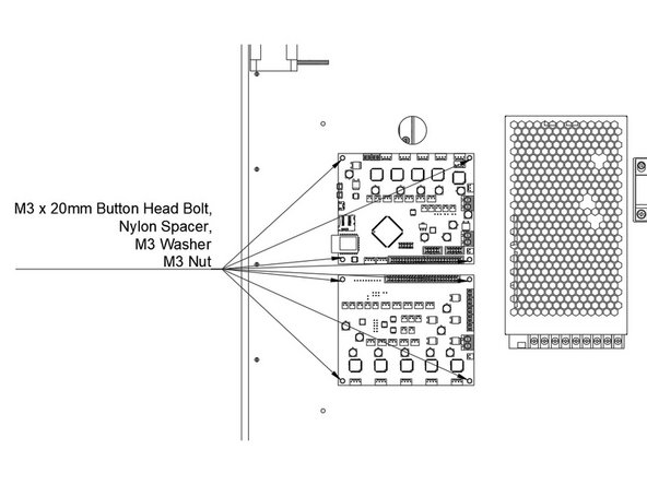
Attach the Duet and Duex5.
-
Be sure the Duet is on top, Duex5 is on bottom.
-
Pay careful attention to the orientation.
-
Mount them by putting one M3 x 16mm bolt through the board. Put the black nylon 5mm tall spacer behind the board.
-
The image says 20mm, it needs to be corrected.
-
Pass the bolts through the panel, attach with an M3 Washer and M3 nut.
If duet3 + raspberry pi then:
The duet 3 goes on top with the Ethernet port facing the front of the printer and ribbon connector facing the bottom.
tThe raspberry pi goes below the duet with the Ethernet facing the front of the printer. The ribbon between them goes under the raspberry pi.
Why can’t they just edit the directions to say M3 x 16 SHCS? I had no M3 X 16 or 20 mm button head screws in my kit.
Jeff Weiss - Resolved on Release Reply
M3 x 16 Button Heads work. I only had 5 M3x20 when I got to this stage
evin powell - Resolved on Release Reply
-
-
-
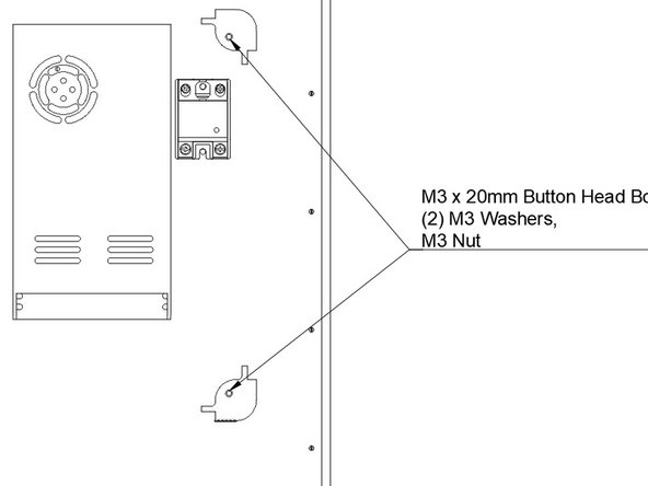
Attach the two rear Ebox Corners.
-
Use an M3 x 16mm Socket Cap Head Screws and washer.
-
Image says 20mm bolt, will be corrected
-
Pass them through the short side of the Ebox corner, and through the right panel.
-
Fasten with an M3 washer and M3 nut.
The Filastruder.com Corner pieces I received were thicker on the bottom so the 16mm screws weren't really long enough but I had mistakenly put inserts in the panel side so the M3 x 16mm Socket Head Cap Screws worked just fine and seems to be holding pretty good.
Jeffery Seiffert - Resolved on Release Reply
-
-
-
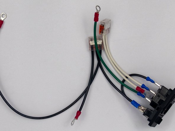
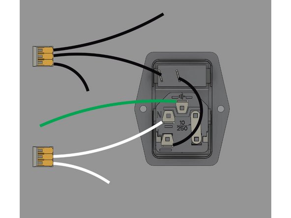
The power switch in your kit should come pre-wired. This guide will walk you through it if it's not, and also serve as a way to double check it.
-
-
-
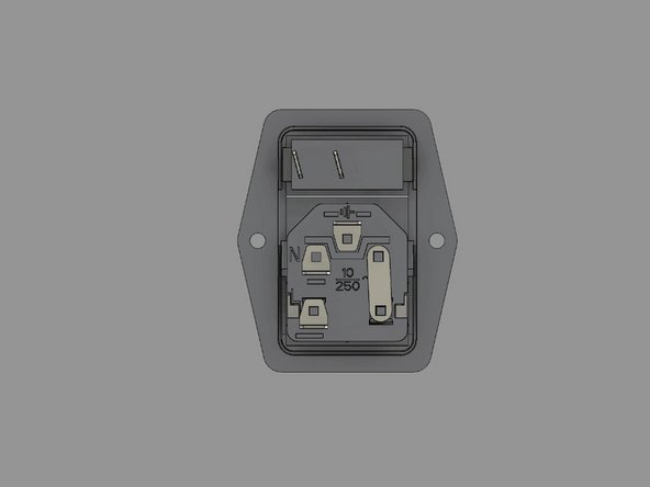
If your switch isn't already wired, lay it face down as shown.
-
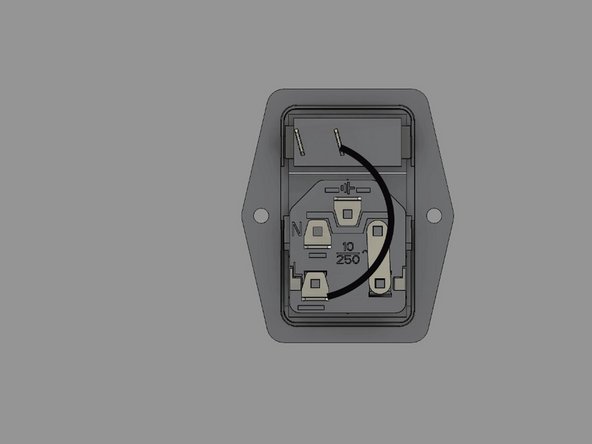
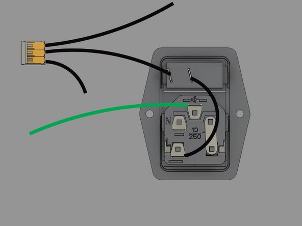
Install the 75mm black wire between the switch and the fuse. It's a short black wire, with a spade terminal on each end.
-
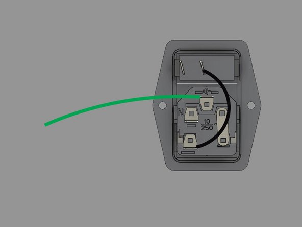
Install the 150mm green ground wire to the ground terminal on the plug. It has a spade terminal on one end, and a ring terminal on the other.
-
-
-
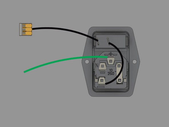
Install the 100mm black wire onto the other terminal on the switch. One end is a spade terminal, the other end is bare wire, and goes into a 3 connector WAGO.
-
Add a 80mm black wire with a ring terminal into one slot in the WAGO, and a 300mm black wire with a ring terminal into the other slot in the wago.
-
-
-
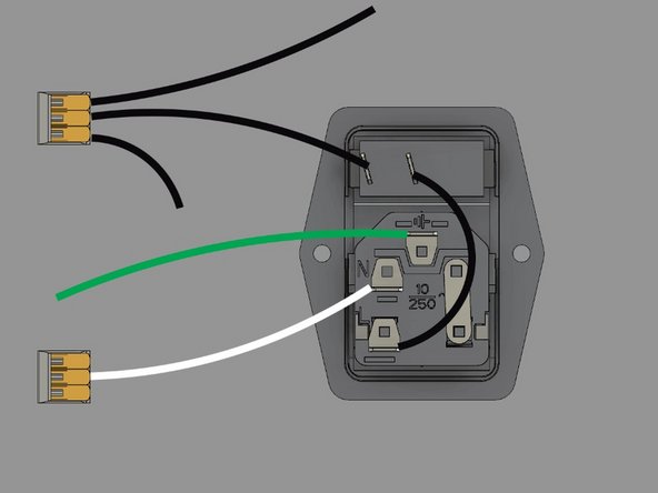
Install a 100mm white wire into the remaining spot on the plug with a spade connector. The other end of the wire is bare, and goes into a 3 slot WAGO connector.
-
Add the bare end of a 100mm white wire into the WAGO. The other end has a ring connector.
-
-
-
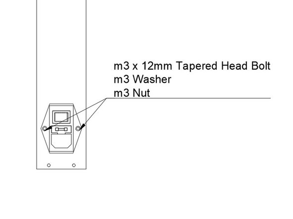
Install the assembled and wired Power Switch / Plug module into the rear Ebox Panel.
-
Pass the wiring already attached to the plug through the panel.
-
Insert (2) M3 x 12mm Tapered Head Bolts through the switch and panel.
-
Fasten using an M3 washer and M3 nut.
-
-
-
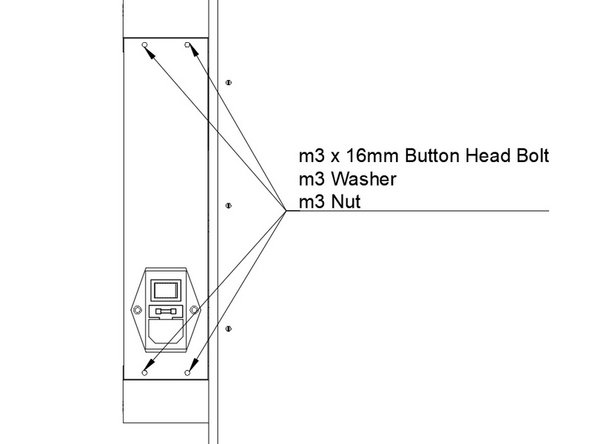
Install the Rear Ebox panel onto the Ebox corners you've installed.
-
Pass an M3 x 16mm Button Head Bolt through each of the panel holes.
-
Fasten each bolt using an M3 washer and M3 nut.
-

Cancel: I did not complete this guide.
10 other people completed this guide.
2 Comments
It would sure be great if there was a Next button on the bottom of the pages to go to the next step. A Previous button too.
Jeffery Seiffert - Resolved on Release Reply
Great to see all of these documents in the same place, finally! The illustrations are very nice.
Aaron Craft - Resolved on Release Reply