
Introduction
It's assumed that you're building a kit from Filastruder, and you've completed all previous sections. At the end of this section you should have all your panels attached to your frame assembly.
-
-
Prior to installing the side and bottom panels, deburr each panel along each edge to avoid injury.
-
It's important that you know which side is which on your frame, so the panels are installed correctly. If you haven't done so, mark the frame with tape, or write on the extrusions to note the front & top, at the least.
-
-
-
When first installing the panels, only snug up the nuts, do not overly tighten them.
-
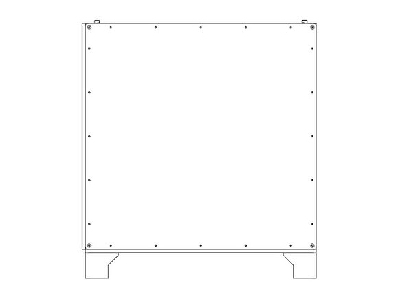
Flip the printer frame upside down, to install the bottom panel first.
-
It's important the two holes are on the same side as the two Z towers (left side), and the "shiny" side of the panel faces out. The holes should be offset towards the front of the printer.
-
It's easiest to start by lining up the bolts close to where they'll need to be. Then start from one corner and work your way along the sides. Needle nose pliers can help to line the bolts up with the holes.
-
For the Feet, put them over the two bolts at each corner, and fasten each with (2) M3 Nylock Nuts. Do not overtighten them against the plastic.
-
Snug down the bottom panel using (3) M3 Nylock Nuts for the other bolts protruding along each side. A final tighten will be done later.
-
-
-
Lay the printer front down on some blocks to protect the bolts.
-
It's important that when looking down at the printer as in the picture, the two Z towers are on the Right side of the image.
-
The "textured" side of the HDPE panel should face out, shiny side in.
-
Install the back panel using (20) M3 Nylock Nuts, in the same method as before. Do not fully tighten the nuts yet.
-
For the ZLT you'll need (24) M3 Nylock Nuts total.
-
-
-
Lay the printer Right side down on some blocks to protect the bolts.
-
It's important that this panel goes on the left end of the printer, which is the end with two Z towers.
-
The "textured" side of the HDPE panel should face out, shiny side in.
-
Install the left panel using (20) M3 Nylock Nuts, in the same method as before. Do not fully tighten the nuts yet.
-
For the ZLT you'll need (24) M3 Nylock Nuts total.
-
-
-
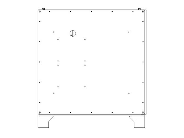
Lay the printer left side down on some blocks.
-
It's important that this panel goes on the side with the single Z tower. Note the position of the hole for the cables to pass through.
-
The "textured" side of the HDPE panel should face out, shiny side in.
-
Install the Right panel using (20) M3 Nylock Nuts, in the same method as before. Do not fully tighten the nuts yet.
-
For the ZLT you'll need (24) M3 Nylock Nuts total.
-
-
-
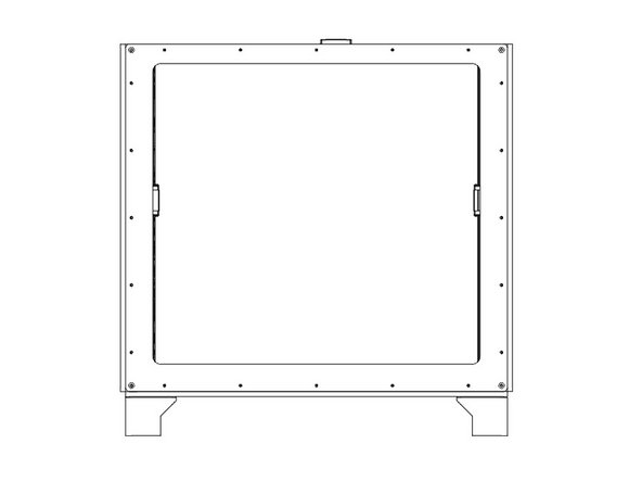
Lay the printer back side down.
-
The "textured" side of the front HDPE panel should face out, shiny side in.
-
The thinner edge of the front panel goes towards the top of the printer.
-
Install the front panel using (20) M3 Nylock Nuts, in the same method as before. Do not fully tighten the nuts yet.
-
For the ZLT you'll need (24) M3 Nylock Nuts total.
-
-
-
If you have a Halo, now is the time to install it. Generally use (1) M3 x 10mm button head bolt bolt and (1) M3 washer per "slot" in the Halo.
-
Center the bolt in the middle slot, and put the bolts in the outside slots at the outside ends of the channels.
-
Be sure to roughly balance the number of M3 nuts between the bolts holding down the Halo.
-
The Stepper Mounts for the Halo go on the right side of the printer, idler mounts to the left.
-
-
-
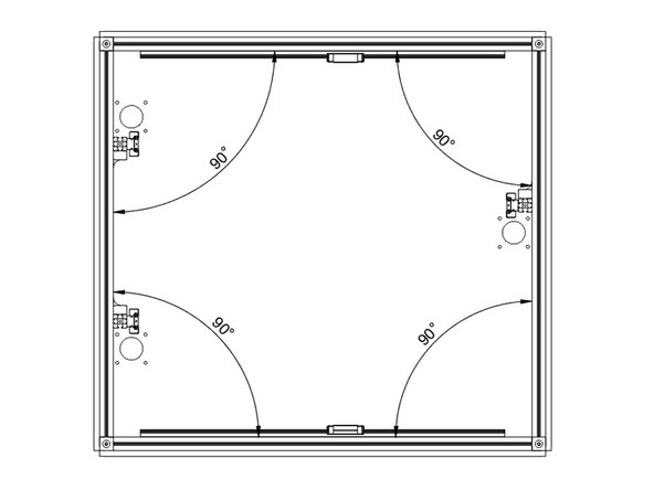
Now is when you want to square up your frame. Start with the bottom panel, and get it as centered and even as you can.
-
With the printer laying on its back. Tighten all 5 nuts (including the feet) along one side of the bottom panel. Use a square or 123 blocks to square up the bottom extrusions, and tighten down the rest of the nuts on the bottom panel.
-
Repeat this process for each of the side panels, tightening the bolts along the bottom of each panel first.
-
Be sure the side panels do not protrude above the top extrusions before tightening them.
-


Cancel: I did not complete this guide.
23 other people completed this guide.
One Comment
The kit panels will interfere/collide on some edges, throwing the frame out of square. The lip of the left panel will block the rear panel from shifting over as needed, for example.
Use a planer or razor to bevel the edges a bit, or even 45-degree edges to allow them to be positioned without hard contact.
Max Plastix - Resolved on Release Reply