-
-
The RailCore Mini is a "DIY" project, build safe, build smart, and be responsible.
-
Build at your own risk.
-
When in doubt, double check things.
-
3D Printers can get very hot, use common sense and quality components.
-
If you need help, find us at the RailCore Facebook page or RailCore Discord channel. Both are linked from RailCore.org.
-
-
-
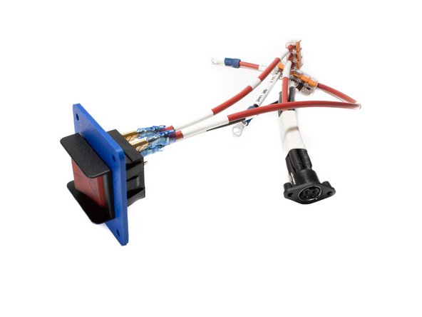
The power switch in your kit should come pre-wired. Below is a cable reference, and also serves as a way to double check it.
-
Pin 1A -> Black, Wago (6 Port) / 150mm
-
Pin 4B -> Red, Wago (3 Port) / 150mm
-
Pin 5B -> Red, Duet VIN (24v) / 250mm
-
-
-
The power input plug in your kit should come pre-wired. Below is a cable reference, and also serves as a way to double check it.
-
Pin 1 -> Black, Wago (6 Port) / 120mm
-
Pin 2 -> Red, Wago (3 Port) / 120mm
-
Pin 3 -> Red, Wago (3 Port) / 120mm
-
Pin 4 -> Black, Wago (6 Port) / 120mm
-
-
-
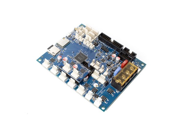
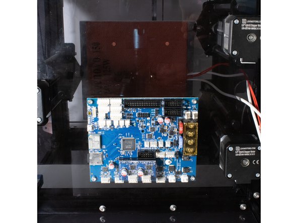
Install the Duet +2 expansion board on the Duet board as shown in the image.
-
Using (4) nylon standoffs, M3 x 16 socket head screws, and M3 washers, attach the Duet to the base of the printer.
-
-
-
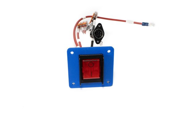
Using (4) M3 x 12 socket head screws, M3 washers, and M3 nuts, install the power switch under the panel.
-
Off position should be towards the top of the printer.
-
-
-
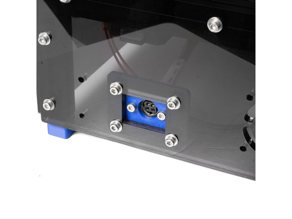
Using (2) M3 x 10 self tapping screws, attach the power plug to the printed mount.
-
The material the plug is made out of can also be tapped for M3.
-
Using (4) M3 x 12 socket head screws, M3 washers, and M3 nuts, install the power plug under the panel.
-
-
-
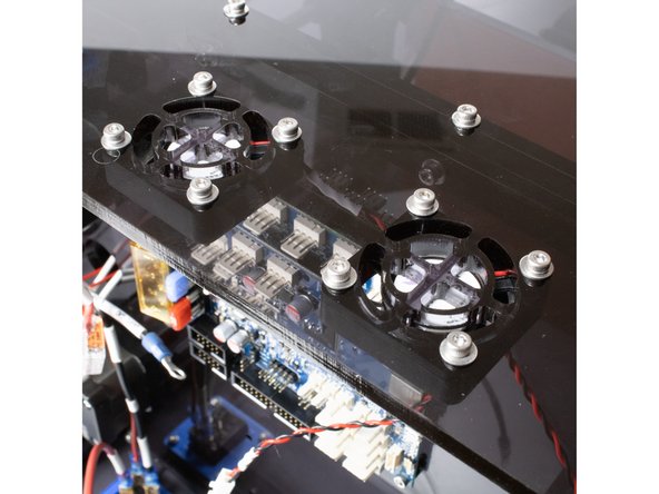
Using (4) M3 x 20 socket head screws, M3 washers, and M3 nuts, install the (2) panel fans under the rear panel.
-