
-
-
The first step is to align your belts. Adjust the steppers so there's some tension - doesn't take much, just enough that the belts are straight.
-
Loosen the bolts holding each stepper and idler mount, and move them on the frame until the belts form 90 degree angles to each other.
-
If you have a Halo, this alignment is done automatically.
-
-
-
Earlier in the process you should have made sure your belts are equal lengths, if you did, that will make getting proper tension easier.
-
Each X Carriage has two bolts retaining the Y rail in place. Loosen those bolts in both carriages just a little before proceeding. (They should still keep the rail in position, but should not be tight)
-
Pull on the Front stepper in the mounts to lightly tension the front belt. You don't need too much tension.
-
Pull the rear stepper back in the mount until the measurements marked in red on the image are equal. (Measure from the right side of the Y rail marked in red, to the left side of the top right extrusion where marked in red).
-
1-2-3 blocks can be used in place of measuring.
-
Once the Y rail is squared you should re-tighten the bolts in the X carriages to retain the Y rail.
-
Ideal belt tension is between 40 - 50hz as measured on the short spans on the left of the printer between the idler mounts.
-
-
-
Loosen all the bolts holding your linear rail to one Z extrusion. Adjust the Rail so it's 20mm above the bottom panel.
-
Tighten only the top bolt holding the rail to the extrusion.
-
Place the Rail Alignment Tool over the linear rail near the bottom bolt. This will center the linear rail on the extrusion. Tighten the bottom bolt.
-
Loosen the top bolt. Now work your way up from the bottom, putting the rail alignment tool near each bolt, then tightening it.
-
Repeat this process for each of your Z rails.
-
Repeat this process for your X rails, working end to end. Center the X rails in the extrusion.
-
-
-
There is a video on aligning the Z towers here: https://www.youtube.com/watch?v=CNWzMLc5...
-
Loosen the bolts in the Z brackets for one tower, so it can move freely.
-
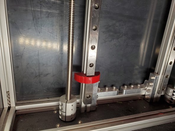
Lower the Z yoke by spinning the lead screw, until the yoke is just above the leadscrew coupler.
-
Tighten down the lower Z bracket, be sure the Z extrusion is pushed flush against the side extrusions as you tighten the brackets.
-
Move the yoke into the center of the Z tower.
-
Use a calipers or a ruler to measure from your front panel to the Z extrusion at the bottom.
-
Repeat the same measurement near the top of the Z tower, and adjust until it's equal.
-
Tighten the top of the Z tower. Repeat for all 3 towers.
-
-
-
Loosen your X endstop mount. Move it to the left side of the rear extrusion.
-
Manually move the Y rail until the hotend is approx 5mm from one of the left leadscrews.
-
Move the X endstop to be against the rear X carriage, be sure the switch triggers.
-
Tighten down the X endstop.
-

Cancel: I did not complete this guide.
11 other people completed this guide.