Introduction
It's assumed that you're building a kit from Filastruder, and you've completed all previous sections. At the end of this section you should have a "bottom extrusions" assembly together for your RailCore frame.
-
-
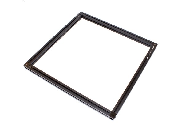
Layout bottom frame as shown. Note that the corner cubes should have a small hole facing up.
-
It is a good idea to mark each extrusion with a bit of masking tape on top, indicating which extrusion it is.
-
-
-
Use (1) M3 x 8mm socket head screw to the 270mm bottom left extrusion. Note the orientation of the corner cube.
-
-
-
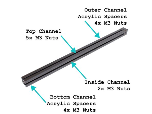
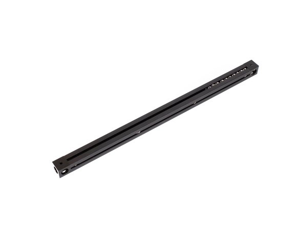
Slide (5) M3 x 16mm hex head bolts into the top channel.
-
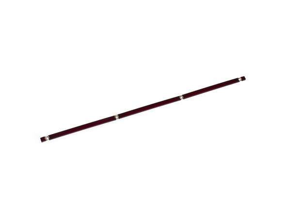
In the layout shown in the second image, insert the acrylic spacer inserts and M3 nuts in the outer channel. There should be (2) 5mm spacers, (3) 81mm spacers, and (4) M3 nuts.
-
Slide (2) M3 nuts into the inside channel. Note: If using a metal bottom (base plate), these are not needed.
-
In the layout shown in the second image, insert the acrylic spacer inserts and M3 nuts in the bottom channel. There should be (2) 5mm spacers, (3) 81mm spacers, and (4) M3 nuts.
-
-
-
Use (1) M3 x 8mm socket head screw to attach the second corner cube to the other end of the bottom left extrusion. Note hole orientation.
-
-
-
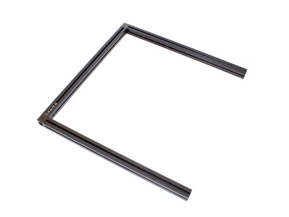
Attach bottom (2) 270mm front and bottom back extrusions using (1) M3 x 8mm socket head screw each.
-
-
-
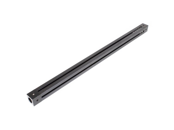
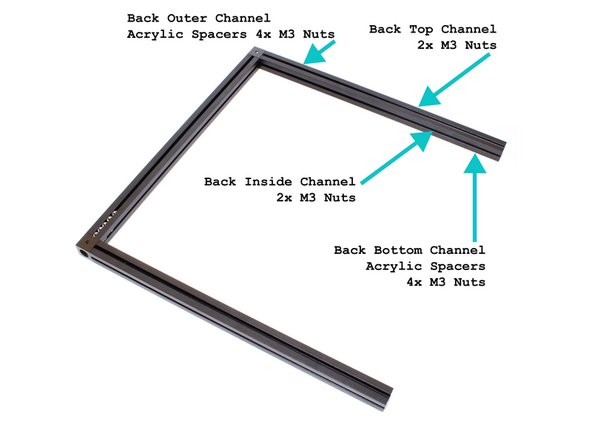
In the layout shown in the third image, insert the acrylic spacer inserts and M3 nuts in the outer and bottom channels of the back extrusion. There should be (2) 5mm spacers, (3) 81mm spacers, and (4) M3 nuts in each.
-
Slide (2) M3 nuts in the top channel of the back extrusion.
-
Slide (2) M3 nuts in the inside channel of the back extrusion.
-
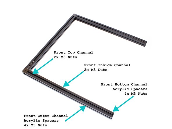
In the layout shown in the third image, insert the acrylic spacer inserts and M3 nuts in the outer and bottom channels of the front extrusion. There should be (2) 5mm spacers, (3) 81mm spacers, and (4) M3 nuts in each.
-
Slide (2) M3 nuts in the inside channel of the front extrusion.
-
Slide (2) M3 nuts in the inside channel of the front extrusion.
-
-
-
Use (1) M3 x 8mm socket head screw to add a corner cube to the bottom right 270mm extrusion. Note the orientation of the corner cube - a small hole needs to face up.
-
-
-
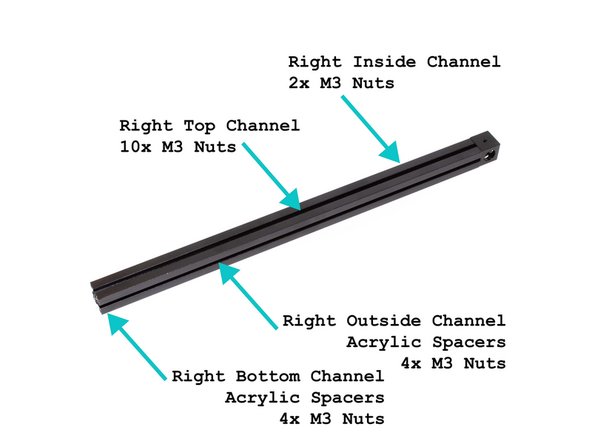
Slide (10) M3 nuts into the top channel.
-
In the layout shown in the second image, insert the acrylic spacer inserts and M3 nuts in the outer channel. There should be (2) 5mm spacers, (3) 81mm spacers, and (4) M3 nuts.
-
Slide (2) M3 nuts into the inside channel.
-
In the layout shown in the second image, insert the acrylic spacer inserts and M3 nuts in the bottom channel. There should be (2) 5mm spacers, (3) 81mm spacers, and (4) M3 nuts.
-
-
-
Use (1) M3 x 8mm socket head screws to attach a second corner cube to the bottom right extrusion. Note the orientation of the corner cube - a small hole should be facing up.
-
-
-
Use (2) M3 x 8mm socket head screws to attach the bottom right extrusion to the rest of the bottom frame assembly from earlier.
-