Tools
No tools specified.
-
-
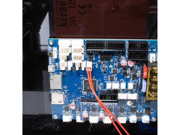
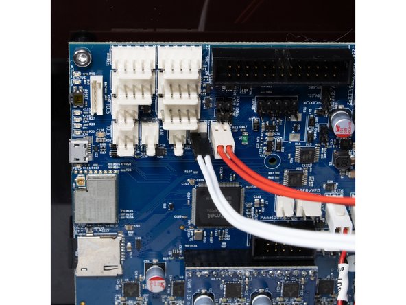
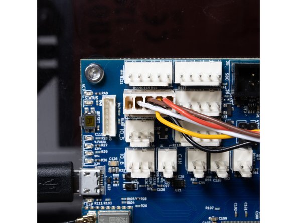
The black wire labeled Duet GND from the 6 slot Wago connector attaches to the first GND on the Duet.
-
The red wire labeled Duet 24v from the 3 slot Wago connector attaches to the first VIN terminal on the Duet.
-
-
-
The ring terminals coming from the bed should attach to the remaining terminals (OUT 0).
-
-
-
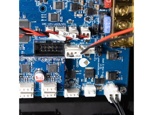
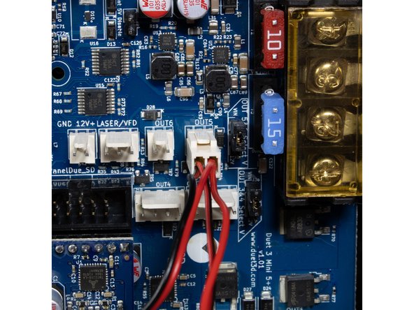
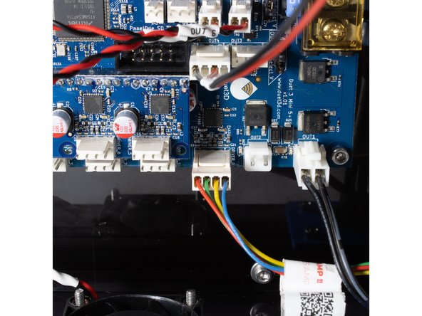
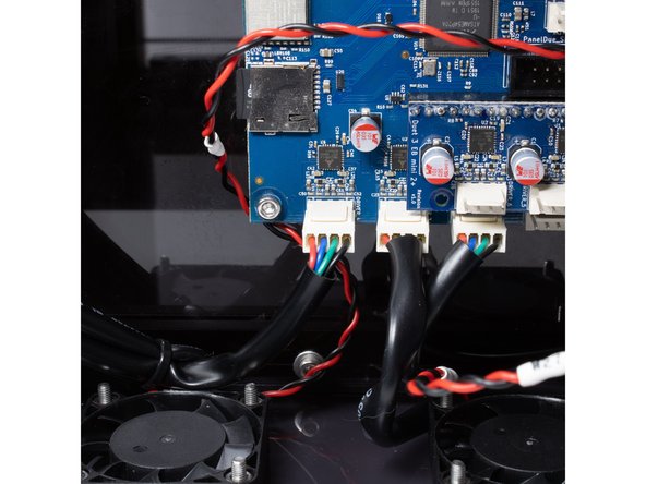
Wire the layer fan to out4.
-
Panel fans are wired to out5.
-
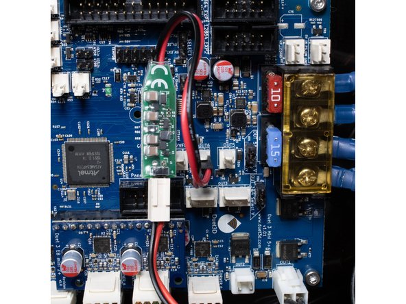
Hotend fan is wired to out6.
-
If you are using the E3D Revo Micro, your hotend fan must use the included 24v -> 5v buck converter.
-
-
-
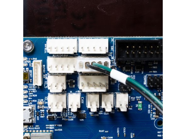
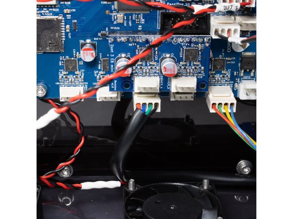
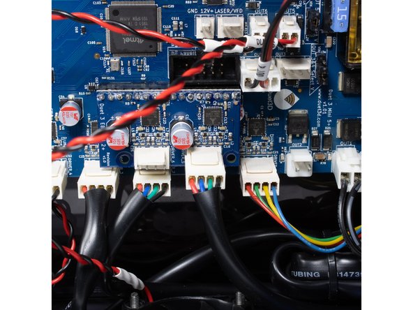
Front right Z stepper is wired to Drive 2.
-
Rear right Z stepper is wired to Drive 3.
-
Left Z stepper is wired to Drive 4.
-
-
-
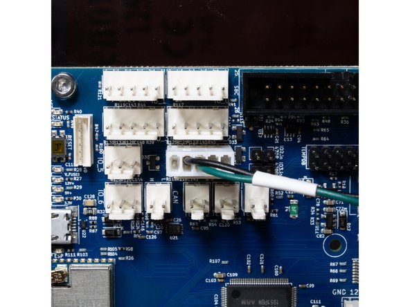
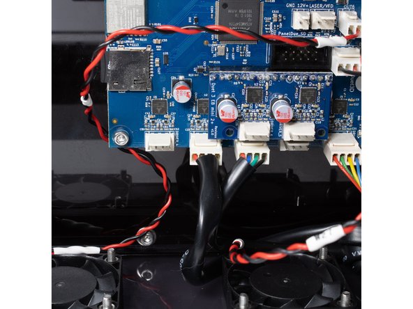
X stepper (front) is wired to Drive 5 on the expansion board.
-
Y stepper (rear) is wired to Drive 6 on the expansion board. This is the last free driver on the expansion board.
-
-
-
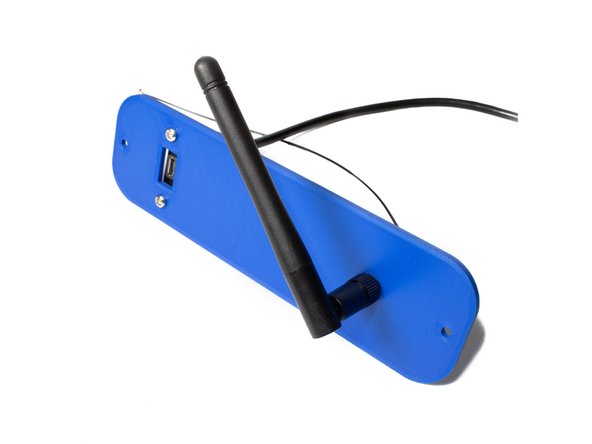
Using (2) M3 x 10 socket head screws, washers and nuts, attach the antenna and USB extender to the outside of the printer panels.
-
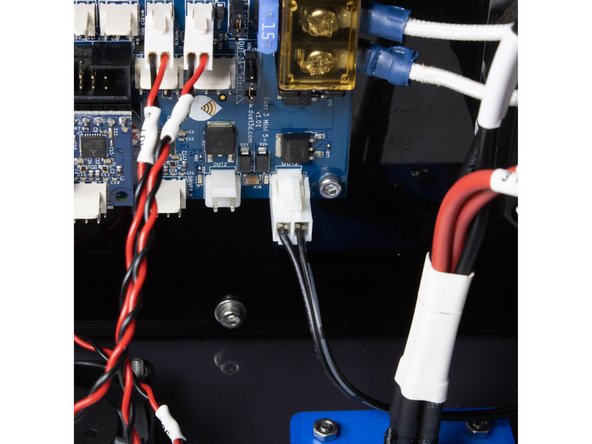
Plug the USB extension and WiFi pigtails into the Duet.
-
-