-
-
Newer Filastruder kits use Socket Cap Head Screws, use them in place of all button head screws in this section unless noted.
-
-
-
THE RAILCORE IS A “DIY” PROJECT - BUILD SAFE, BUILD SMART, AND BE RESPONSIBLE.
-
BUILD AT YOUR OWN RISK.
-
WHEN IN DOUBT, DOUBLE CHECK THINGS.
-
3D PRINTERS CAN GET VERY HOT. USE COMMON SENSE AND QUALITY COMPONENTS.
-
If you need help, find us at the RailCore Facebook page or RailCore Discord channel. Both are linked from RailCore.org
-
-
-
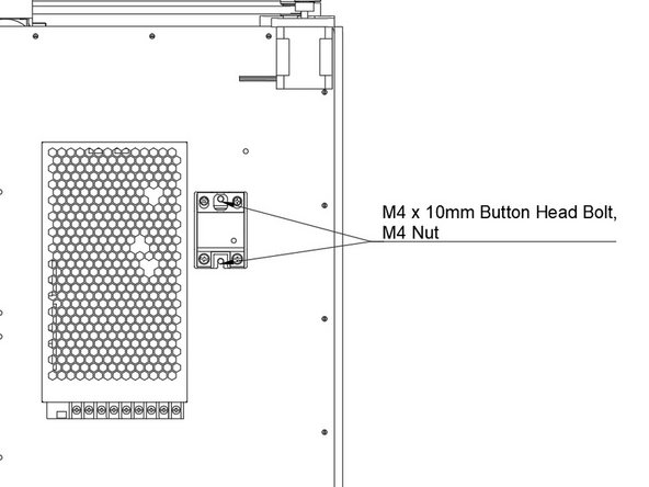
Check the voltage setting on the side of your Power Supply before installing it.
-
Attach the PSU using (4) M4 x 10mm Button Head Bolts. The bolts go through holes in the right panel, and into the back of the PSU.
-
Be sure to install the PSU so the wiring terminals are to the bottom of the printer.
-
-
-
Install the SSR as shown.
-
Each hole is held in place using (1) M4 x 10mm Socket Cap Head Screws.
-
-
-
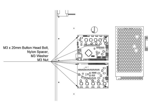
Attach the Duet and Duex5.
-
Be sure the Duet is on top, Duex5 is on bottom.
-
Pay careful attention to the orientation.
-
Mount them by putting one M3 x 16mm bolt through the board. Put the black nylon 5mm tall spacer behind the board.
-
The image says 20mm, it needs to be corrected.
-
Pass the bolts through the panel, attach with an M3 Washer and M3 nut.
-
-
-
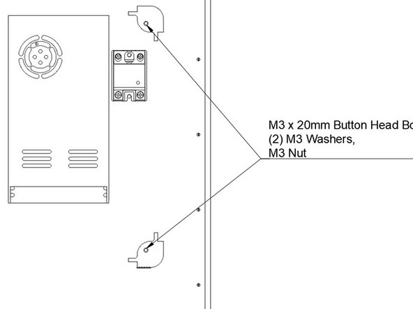
Attach the two rear Ebox Corners.
-
Use an M3 x 16mm Socket Cap Head Screws and washer.
-
Image says 20mm bolt, will be corrected
-
Pass them through the short side of the Ebox corner, and through the right panel.
-
Fasten with an M3 washer and M3 nut.
-
-
-
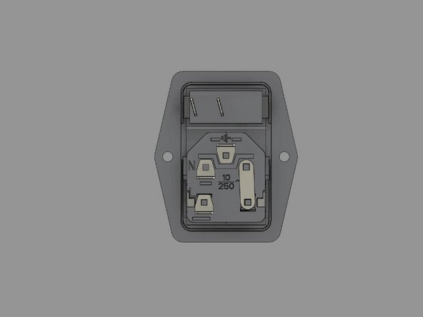
The power switch in your kit should come pre-wired. This guide will walk you through it if it's not, and also serve as a way to double check it.
-
-
-
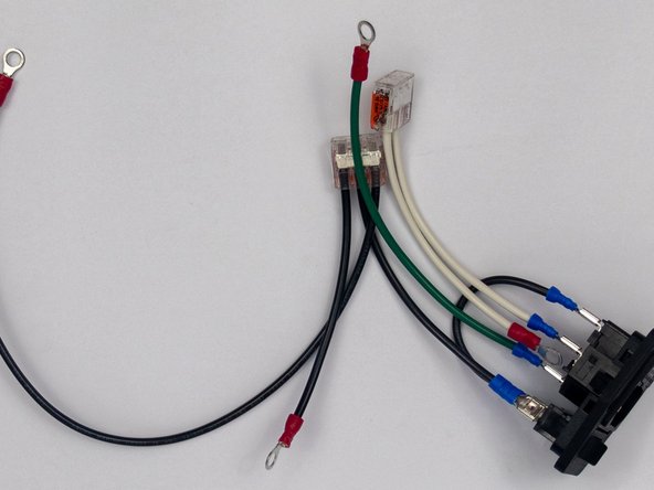
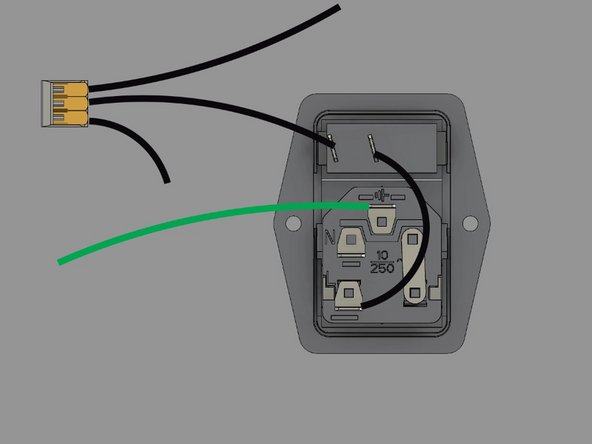
If your switch isn't already wired, lay it face down as shown.
-
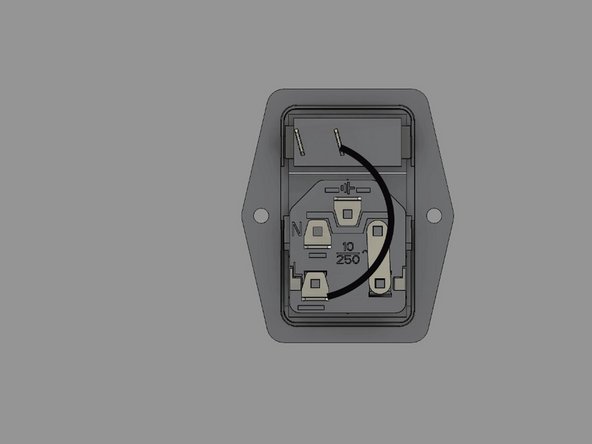
Install the 75mm black wire between the switch and the fuse. It's a short black wire, with a spade terminal on each end.
-
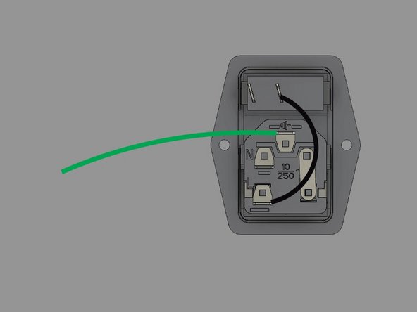
Install the 150mm green ground wire to the ground terminal on the plug. It has a spade terminal on one end, and a ring terminal on the other.
-
-
-
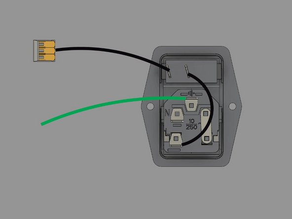
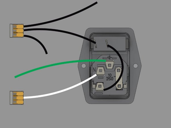
Install the 100mm black wire onto the other terminal on the switch. One end is a spade terminal, the other end is bare wire, and goes into a 3 connector WAGO.
-
Add a 80mm black wire with a ring terminal into one slot in the WAGO, and a 300mm black wire with a ring terminal into the other slot in the wago.
-
-
-
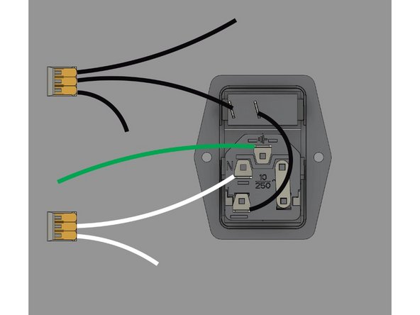
Install a 100mm white wire into the remaining spot on the plug with a spade connector. The other end of the wire is bare, and goes into a 3 slot WAGO connector.
-
Add the bare end of a 100mm white wire into the WAGO. The other end has a ring connector.
-
-
-
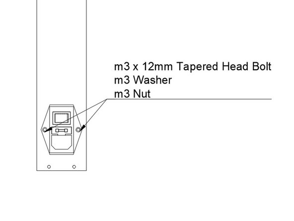
Install the assembled and wired Power Switch / Plug module into the rear Ebox Panel.
-
Pass the wiring already attached to the plug through the panel.
-
Insert (2) M3 x 12mm Tapered Head Bolts through the switch and panel.
-
Fasten using an M3 washer and M3 nut.
-
-
-
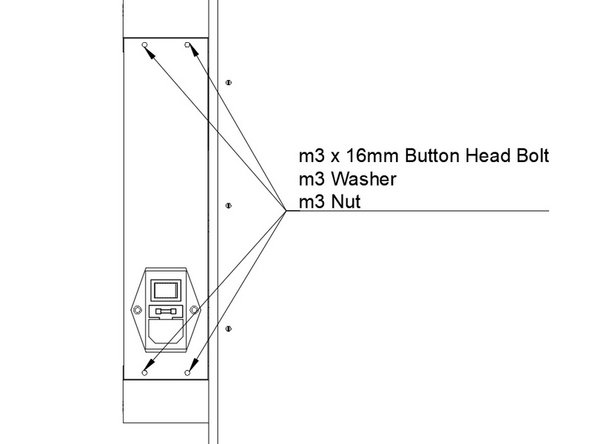
Install the Rear Ebox panel onto the Ebox corners you've installed.
-
Pass an M3 x 16mm Button Head Bolt through each of the panel holes.
-
Fasten each bolt using an M3 washer and M3 nut.
-