Difficulty
Moderate
Steps
35
Time Required
02:00:00
- B) Prep 1 step
- C) Top Extrusions Assembly 12 steps
- D) Bottom Extrusions Assembly 10 steps
- E) Upright Extrusion / Frame Final Assembly 3 steps
- F) Z Installation 9 steps

In Progress
This guide is currently being written. Reload periodically to see the latest changes.

User-Contributed Guide
This guide is not managed by the site's staff.

Private
This guide will not appear in search results and can only be viewed by team members!
Introduction
It's assumed that you're building a kit from Filastruder, and you've completed all previous sections. At the end of this section you should have a complete frame assembled for your RailCore.
-
-
You need to use a soldering iron to carefully sink the brass inserts into the printed Y carriage. Sink the inserts in 2/3 of the way, then press the carriage against a flat metal surface to get them flush.
-
After placing each insert you may need to clear the channel by running a tap or bolt down through the insert and into the plastic. (Be very careful not to cross thread your inserts!)
-
Here's a good article about setting the brass heat set inserts: click here.
-
The Y carriage gets (17) 3mm brass inserts, as in the picture. (Note: there are also two on the back side, and one on the top. Not all RailCore kits include the optional one on the top, requiring only 17 inserts)
-
-
-
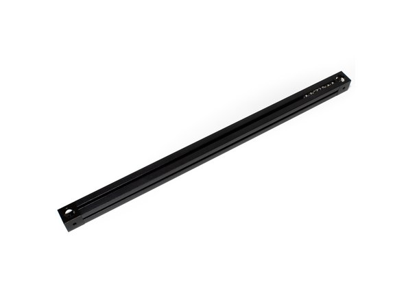
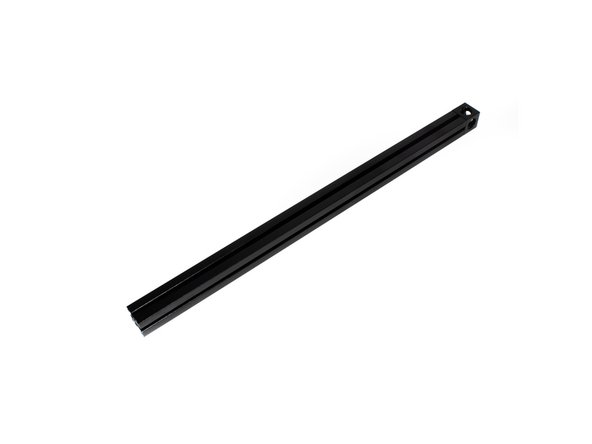
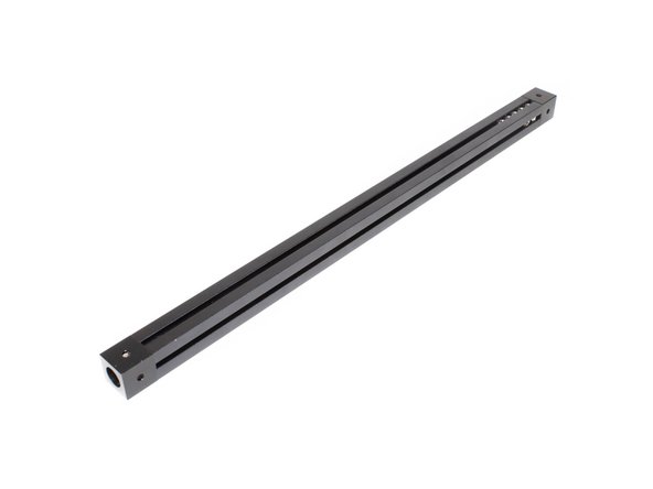
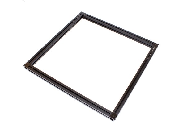
Lay out top extrusions as pictured.
-
It can be helpful to use masking tape to add a label to the top of each extrusion indicating which it is (Top Back, Top Left, etc).
-
Be sure the Corner cubes have a larger hole facing up, smaller hole facing down.
-
-
-
Bolt corner cube to top left 270mm extrusion using (1) M3 x 8mm socket head screw.
-
Note on the corner cube, the small hole is pointing to the right in this image.
-
-
-
Hold the extrusion as it will be oriented on the printer (make sure the big hole on the corner cube faces up).
-
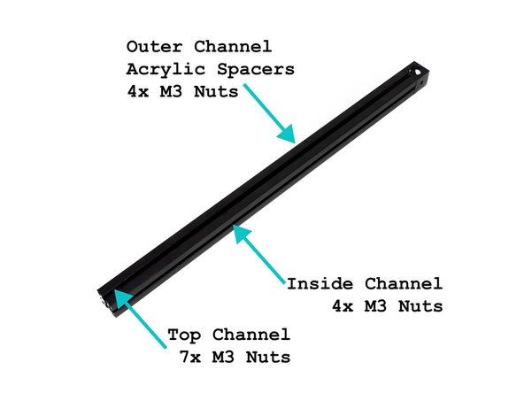
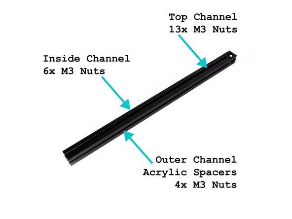
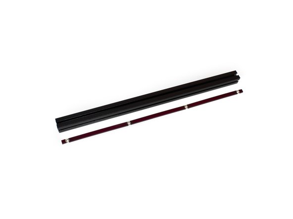
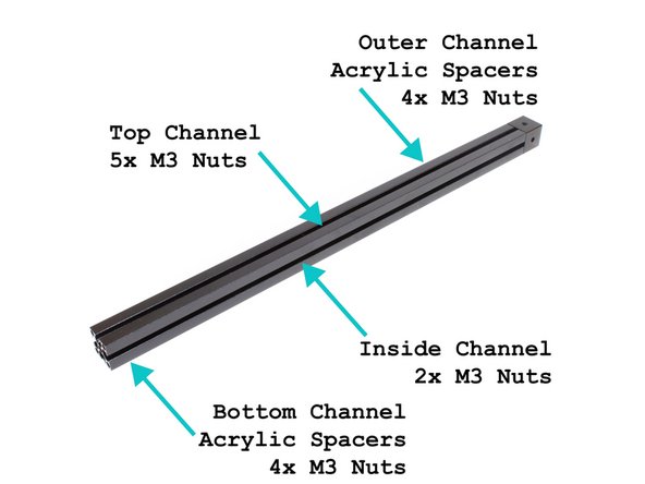
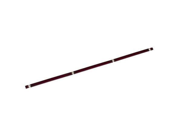
In the layout shown in the image, insert the acrylic spacer inserts and M3 nuts in the outer channel. There should be (2) 5mm spacers, (3) 81mm spacers, and 4 M3 nuts.
-
Slide (7) M3 nuts into the top channel.
-
Slide (4) M3 nuts into the top channel.
-
Note on the corner cube, the small hole is pointing to the right in this image.
-
-
-
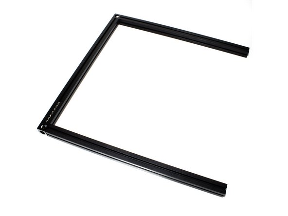
Attach the second corner cube to the top left extrusion using (1) M3 x 8mm socket cap screw. Be sure the large hole is up, small hole is down.
-
Note on both corner cubes, the small hole is pointing to the right in this image
-
-
-
Attach the (2) 245mm top front and top back extrusions using (1) M3 x 8mm socket head screw for each.
-
-
-
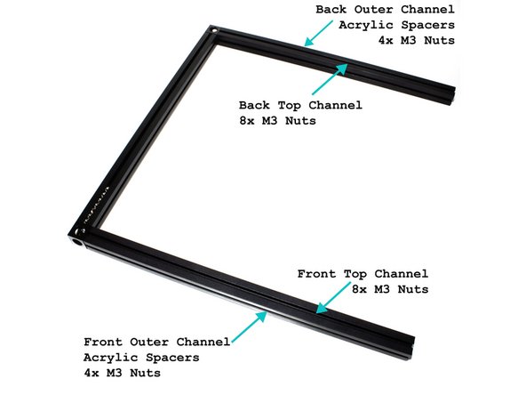
(8) M3 nuts go in the top channel of the back extrusion.
-
(8) M3 nuts go in the front channel of the front extrusion.
-
Insert the acrylic spacer inserts and M3 nuts in the top outer channel. There should be (2) 5mm spacers, (3) 81mm spacers, and 4 M3 nuts (See second image for reference).
-
Insert the acrylic spacer inserts and M3 nuts in the front outer channel. There should be (2) 5mm spacers, (3) 81mm spacers, and 4 M3 nuts (See second image for reference).
-
-
-
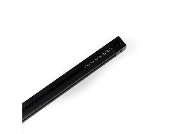
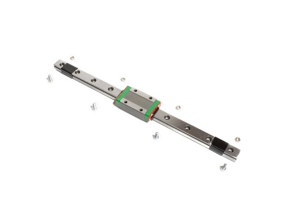
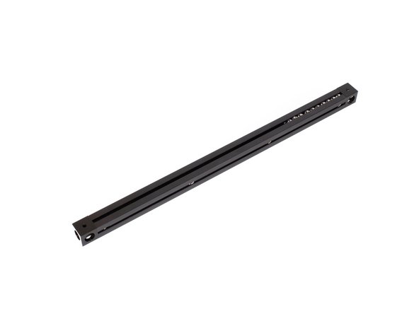
Select 4 evenly spaced holes in your linear rail. (2 empty holes between each bolt)
-
Place a M3 x 8mm socket cap head screw into one of the holes selected. Loosely thread on (1) M3 nut to the bolt. DO NOT TIGHTEN THEM FULLY. The M3 nut only needs to be threaded onto the tip of the bolt, you want a gap between the nut and the back of the rail. Repeat for the other three (3) holes.
-
Repeat the above steps for the other 245mm rail.
-
If you are using Misumi rails, use a M3 lock washer between the M3 x 8mm and the rail.
-
It is highly recommended to use a bit of masking tape to keep the carriage from sliding off of the linear rail.
-
-
-
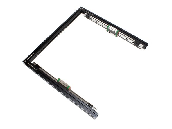
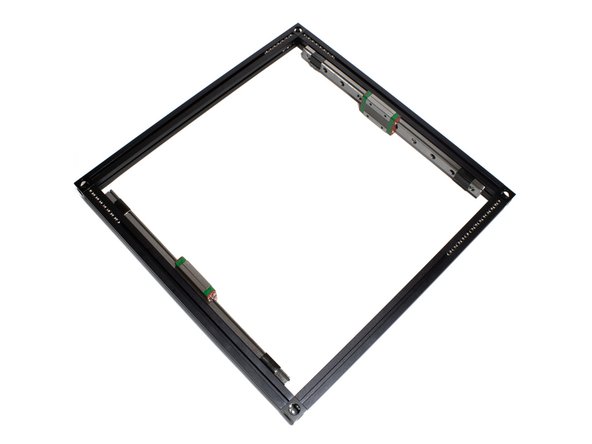
Attach each linear rail to top front and top back extrusions by sliding the M3 nuts into the inside channel on the extrusion.
-
Roughly center the extrusion, and then snug up the bolts.
-
Do not overtighten the bolts, you just need them snug for now. They'll be tightened later.
-
-
-
Set aside the rest of your top extrusion assembly for now, so we can work on the top right extrusion.
-
Attach a corner cube to the right 270mm extrusion using (1) M3 x 8mm socket head screw.
-
-
-
Slide (13) M3 nuts into the top channel.
-
Slide (6) M3 nuts into the inside channel.
-
Insert the acrylic spacer inserts and M3 nuts in the outer channel. There should be (2) 5mm spacers, (3) 81mm spacers, and (4) M3 nuts (See second image for reference).
-
Be sure the orientation of the corner cube is correct. A large hole should face up, a small hole should be facing down, and a small hole should be facing towards the inside channel.
-
-
-
Attach second corner cube to top right extrusion using (1) M3 x 8mm socket head screw.
-
-
-
Attach Top Right Extrusion to the rest of the Top Extrusion Assembly using (2) M3 x 8mm socket head screws.
-
-
-
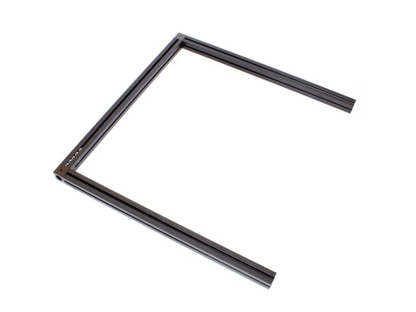
Layout bottom frame as shown. Note that the corner cubes should have a small hole facing up.
-
It is a good idea to mark each extrusion with a bit of masking tape on top, indicating which extrusion it is.
-
-
-
Use (1) M3 x 8mm socket head screw to the 270mm bottom left extrusion. Note the orientation of the corner cube.
-
-
-
Slide (5) M3 x 16mm hex head bolts into the top channel.
-
In the layout shown in the second image, insert the acrylic spacer inserts and M3 nuts in the outer channel. There should be (2) 5mm spacers, (3) 81mm spacers, and (4) M3 nuts.
-
Slide (2) M3 nuts into the inside channel. Note: If using a metal bottom (base plate), these are not needed.
-
In the layout shown in the second image, insert the acrylic spacer inserts and M3 nuts in the bottom channel. There should be (2) 5mm spacers, (3) 81mm spacers, and (4) M3 nuts.
-
-
-
Use (1) M3 x 8mm socket head screw to attach the second corner cube to the other end of the bottom left extrusion. Note hole orientation.
-
-
-
Attach bottom (2) 270mm front and bottom back extrusions using (1) M3 x 8mm socket head screw each.
-
-
-
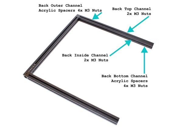
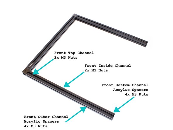
In the layout shown in the third image, insert the acrylic spacer inserts and M3 nuts in the outer and bottom channels of the back extrusion. There should be (2) 5mm spacers, (3) 81mm spacers, and (4) M3 nuts in each.
-
Slide (2) M3 nuts in the top channel of the back extrusion.
-
Slide (2) M3 nuts in the inside channel of the back extrusion.
-
In the layout shown in the third image, insert the acrylic spacer inserts and M3 nuts in the outer and bottom channels of the front extrusion. There should be (2) 5mm spacers, (3) 81mm spacers, and (4) M3 nuts in each.
-
Slide (2) M3 nuts in the inside channel of the front extrusion.
-
Slide (2) M3 nuts in the inside channel of the front extrusion.
-
-
-
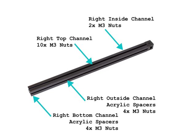
Use (1) M3 x 8mm socket head screw to add a corner cube to the bottom right 270mm extrusion. Note the orientation of the corner cube - a small hole needs to face up.
-
-
-
Slide (10) M3 nuts into the top channel.
-
In the layout shown in the second image, insert the acrylic spacer inserts and M3 nuts in the outer channel. There should be (2) 5mm spacers, (3) 81mm spacers, and (4) M3 nuts.
-
Slide (2) M3 nuts into the inside channel.
-
In the layout shown in the second image, insert the acrylic spacer inserts and M3 nuts in the bottom channel. There should be (2) 5mm spacers, (3) 81mm spacers, and (4) M3 nuts.
-
-
-
Use (1) M3 x 8mm socket head screws to attach a second corner cube to the bottom right extrusion. Note the orientation of the corner cube - a small hole should be facing up.
-
-
-
Use (2) M3 x 8mm socket head screws to attach the bottom right extrusion to the rest of the bottom frame assembly from earlier.
-
-
-
Use (1) M3 x 8mm socket head screws to attach each of the (4) 270mm upright extrusions to the corner cubes on the bottom frame assembly.
-
-
-
Insert acrylic spacers in all extrusion channels facing the outside of the frame. Each extrusion has two outer facing channels.
-
In the layout shown in the second image, insert the acrylic spacer inserts and M3 nuts in all 8 of the outer facing channels. There should be (2) 5mm spacers, (3) 81mm spacers, and (4) M3 nuts in each channel.
-
Insert (2) M3 nuts in each of the remaining 8 channels.
-
-
-
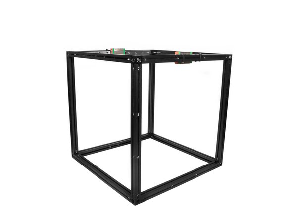
Use (4) M3 x 8mm Socket Cap Head Screws to attach the top extrusion assembly to the upright extrusions.
-
Be sure both the bottom and top frame pieces are in the right orientation. The top right extrusion should have (13) M3 nuts in it's top channel. The bottom right extrusion should have (10) M3 nuts in it's top channel.
-
-
-
Using (16) M3x10 socket head screws and (16) M3 washers, attach the bottom to the frame.
-
Loosen your corner cubes when attaching the bottom or sides to the frame. The acrylic pieces will attempt to pull the frame into square.
-
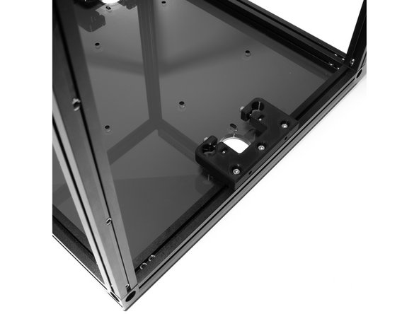
Be sure the bottom panel is in the right orientation.
-
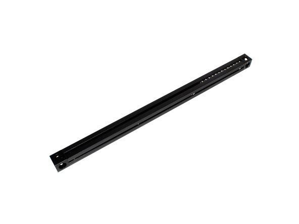
The side with (5) large holes should be on the right side of the printer. For reference, the bottom right extrusion should have (10) M3 nuts in it's top channel.
-
There are (2) sets of (4) holes for mounting the electronics. The larger pattern is for the Duet, and the smaller for an optional Raspberry Pi. The Duet holes should be closer to the back of the printer.
-
-
-
Each Z tower consists of the following printed parts: (1) printed Z yoke and (2) printed Z rod holders.
-
For each printed part insert (2) M3 nuts and (2) M3 x 20 socket head screws. You should do this for all 9 of the printed parts.
-
-
-
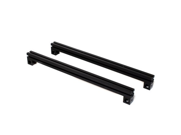
The top of the Z towers will fasten to horizontal extrusions on the left and right sides of the frame.
-
Attach corner cubes to opposing ends of the extrusion with (1) M3 nuts inside the extrusion channel and (1) M3 x 6 socket head screw for each corner cube.
-
A small hole should face up and towards the outside of the extrusion. Use the image as a reference.
-
-
-
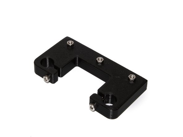
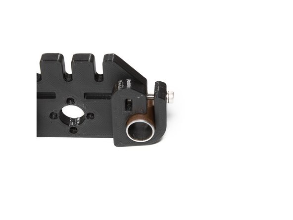
Set aside 3 printed Z rod holders. Using (3) M3 nuts and (3) M3 x 10 socket head screws, prepare each rod holder to slide into the extrusions.
-
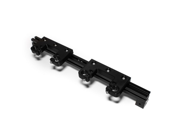
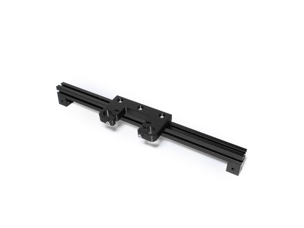
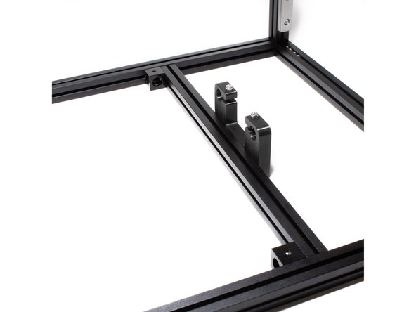
Mount (2) Z rod holders to the right extrusion by sliding the M3 nuts into the top channel. Place (2) M3 nuts into the channel between the (2) rod holders. Tighten the Z rod holders to the extrusion just enough to keep them from moving freely.
-
Mount (1) Z rod holders to the right extrusion by sliding the M3 nuts into the top channel. Tighten the Z rod holder to the extrusion just enough to keep them from moving freely.
-
Note the proper orientation of the Z rod holders and corner cubes using the provided images.
-
-
-
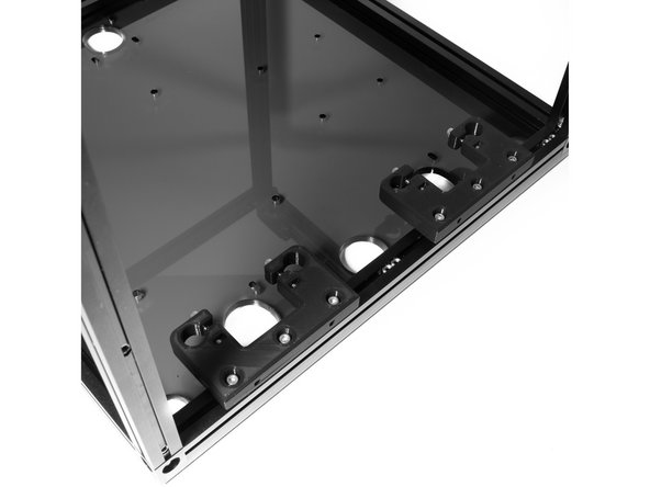
On the right side of the frame, attach (2) Z rod holders to the bottom right extrusion using (6) M3 x 10 socket head screws.
-
On the left side of the frame, attach (1) Z rod holder to the bottom right extrusion using (3) M3 x 10 socket head screws.
-
-
-
Attach both the left and right Z rod holder extrusions to the frame using the corner cubes and existing M3 nuts in the inside channels.
-
Using M3 x 6 socket head screws for each corner cube, attach each to the frame. Do not tighten the corner cubes to the frame at this point.
-
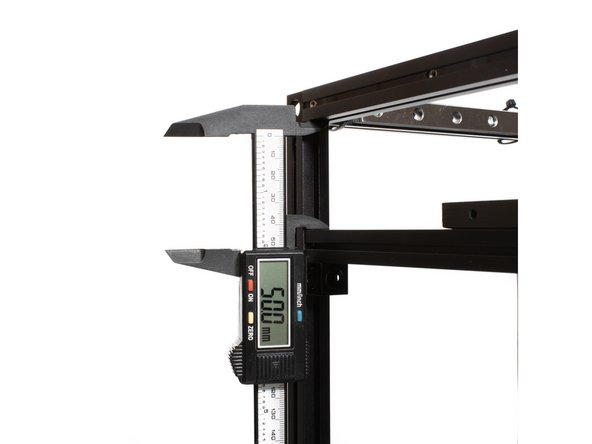
Use calipers to measure the distance between the bottom of the top extrusion, and the top of the Z rod holder extrusion. Tighten the corner cubes to the frame leaving a gap of 50mm as shown in the image.
-
This step is easier with the frame on it's side.
-
-
-
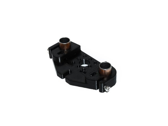
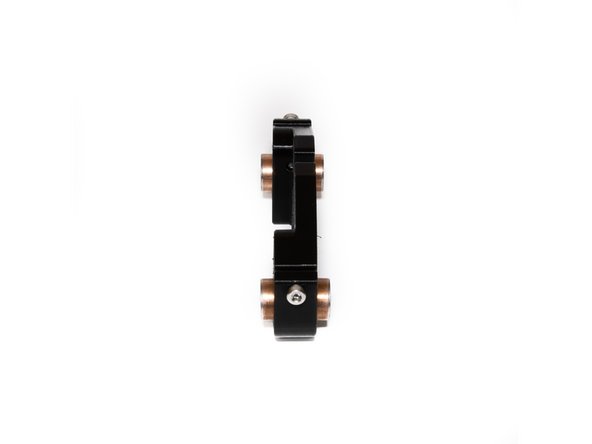
In each printed Z yoke, insert (2) bushings.
-
Center the bushings as shown before tightening the (2) M3 x 20 socket head screws you installed earlier.
-
Be careful not to overtighten. they do not need to be tightened past the point of the printed faces of the clamp being parallel.
-
-
-
Loosen the M3 x 10 socket head screws holding the Z rod holders to the frame.
-
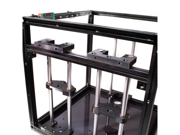
Slide the (6) smooth rods through the top Z rod holder and through the Z yokes. Each Z yoke should be facing flat side up.
-
Fasten the (6) smooth rods to the Z rod holders by tightening the M3 x 20 socket head screws.
-
The top of the smooth rods should be flush with the top of Z rod holders.
-
-
-
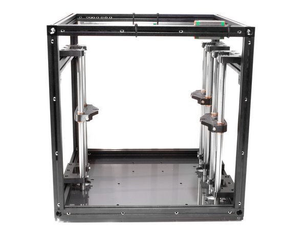
Center each of assembled Z towers over their corresponding motor mount holes in the base of the frame.
-
Tighten down each of the towers to the frame.
-