Difficulty
Moderate
Steps
8
Time Required
02:00:00
- F) Z Installation 8 steps

In Progress
This guide is currently being written. Reload periodically to see the latest changes.

User-Contributed Guide
This guide is not managed by the site's staff.

Private
This guide will not appear in search results and can only be viewed by team members!
Quiz
0
Introduction
It's assumed that you're building a kit from Filastruder, and you've completed all previous sections. At the end of this section you should have a complete frame assembled for your RailCore.
-
-
Using (16) M3x10 socket head screws and (16) M3 washers, attach the bottom to the frame.
-
Loosen your corner cubes when attaching the bottom or sides to the frame. The acrylic pieces will attempt to pull the frame into square.
-
Be sure the bottom panel is in the right orientation. The side with (5) large holes should be on the right side of the printer. For reference, the bottom right extrusion should have (10) M3 nuts in it's top channel.
-
-
-
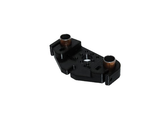
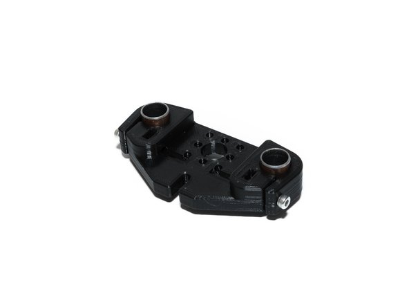
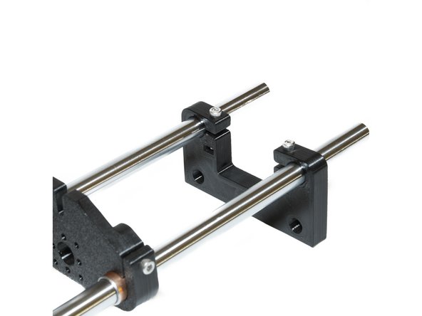
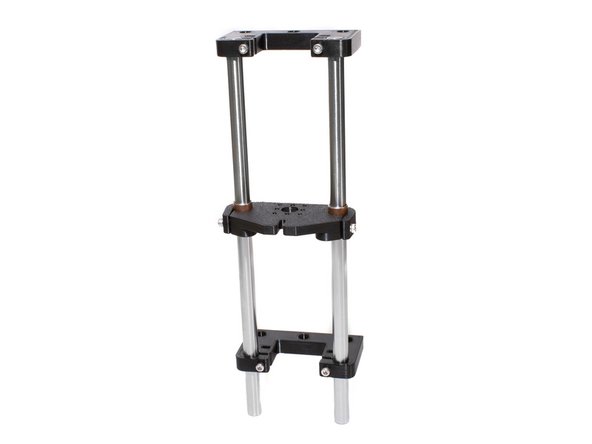
Each Z tower consists of the following printed parts: (1) printed Z yoke and (2) printed Z rod holders.
-
-
-
Insert (2) sleave bearings into Z yoke.
-
Insert (2) M3 nuts into Z yoke.
-
Using (2) M3 x 20 socket head screws, tighten the z yoke to the bearings.
-
Do not overtighten the screws or you may damage the printed part.
-
-
-
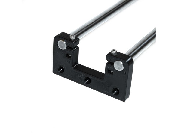
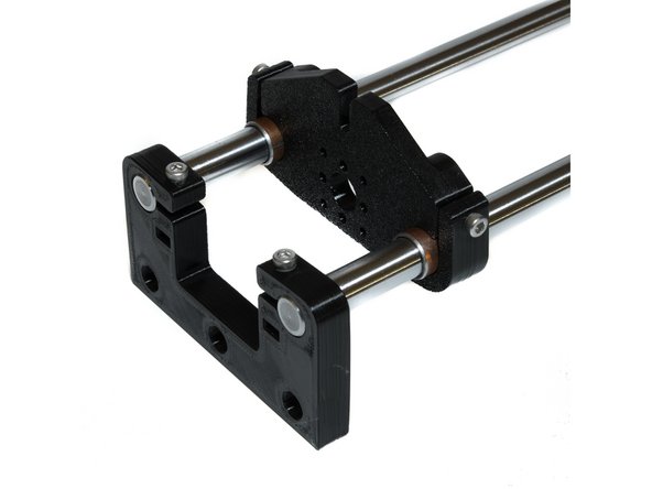
Using (2) M3 nuts and (2) M3 x 20 socket head screws, tighten a Z rod holder to the smooth rods. The rod top of the Z rod holder should be flush with the top of the smooth rods.
-
Slide the Z yoke on the smooth rods.
-
Using (2) M3 nuts and (2) M3 x 20 socket head screws, attach a Z rod holder to the bottom of the smooth rods, leaving about 15mm of smooth rod at the bottom.
-
Use the images provided for proper orientation of printed parts.
-
-
-
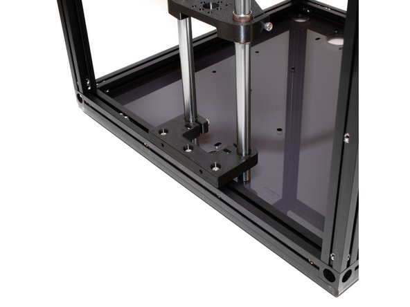
Attach a Z tower to the left side of the frame using (3) M3 x 10 socket head screws. Any spare M3 nuts should be towards the back of the frame.
-
Smooth rods for all Z towers should be flush with the bottom acrylic panel.
-
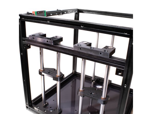
Attach the remaining two Z towers to the right side of the frame using (6) M3 x 10 socket head screws. (2) M3 nuts should be left between the towers for attaching a wire loom retainer. Any spare M3 nuts should be towards the back of the frame.
-
There is no need to worry about alignment at this point. Center the Z rod holders over the mounting holes for the Z motors as best you can for now.
-
-
-
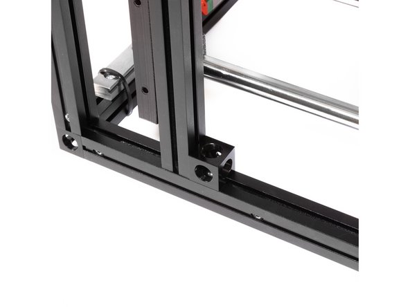
Each tower brace is assembled with (2) corner cubes, (2) M3 nuts, and (2) M3 x 6mm button head screws.
-
Attach corner cubes by sliding a M3 nut into the bottom of the extrusion and fastening with a M3 x 6 mm button head screw.
-
One extrusion should have (3) M3 nuts in the top channel, and the other (8). These will be used to attach the Z rod holders to the brace.
-
Corner cubes should be oriented with a small hole facing the bottom side and the outside of the extrusion.
-
-
-
Using (3) M3 x 10 socket head screws for each tower, fasten the Z rod holders to the braces using the M3 nuts in the top channel of the extrusion.
-
The right side brace should have (8) M3 nuts in the top channel. The two spare nuts should be left between the two Z towers.
-
-
-
Using the existing M3 nuts in the inside extrusion channels, attach the corner cubes to the frame using M3 x 6 button head screws.
-
Laying the frame on it's side will make it easier to align the M3 nuts.
-