Difficulty
Moderate
Steps
6
Time Required
01:00:00
- C) Top Extrusions Assembly 6 steps

In Progress
This guide is currently being written. Reload periodically to see the latest changes.

User-Contributed Guide
This guide is not managed by the site's staff.

Private
This guide will not appear in search results and can only be viewed by team members!
Quiz
0
-
-
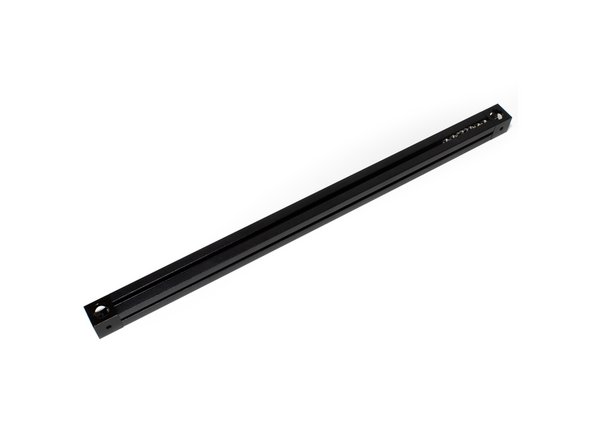
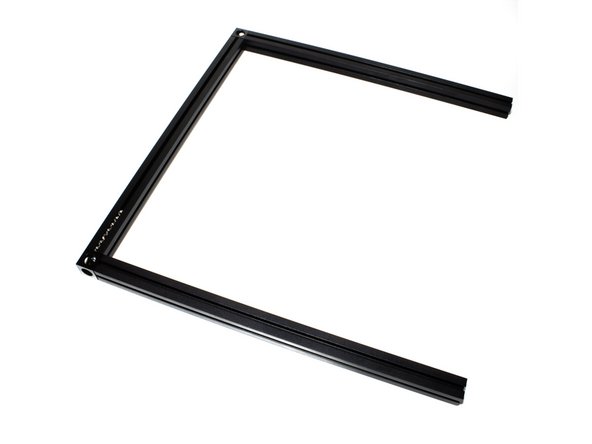
Lay Out Top Extrusions as pictured.
-
It can be helpful to use masking tape to add a label to the top of each extrusion indicating which it is (Top Back, Top Left, etc).
-
Be sure the Corner cubes have a larger hole facing up, smaller hole facing down.
-
-
-
Bolt Corner Cube to Top Left 270mm Extrusion using (1) M3 x 8mm Socket Head Cap Screw.
-
Note on the corner cube, the small hole is pointing to the right in this image.
-
-
-
Hold the Extrusion as it will be oriented on the printer (make sure the big hole on the corner cube faces up).
-
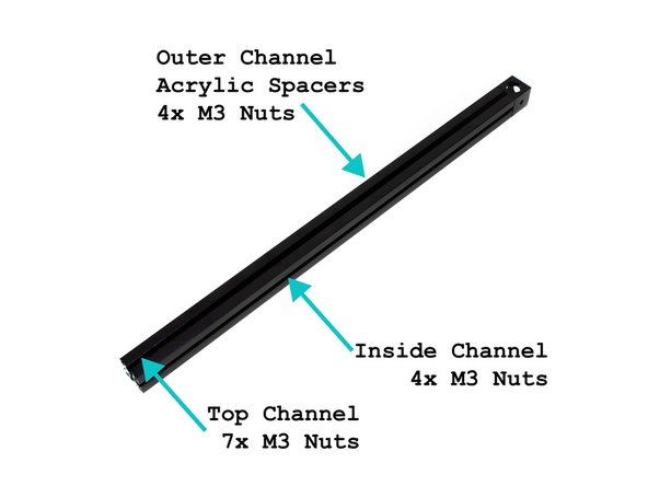
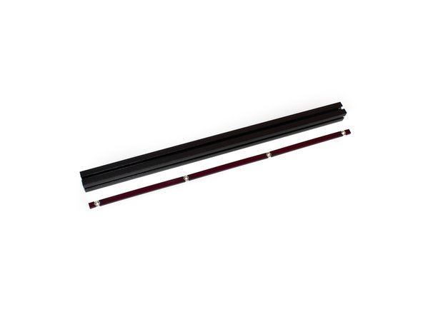
In the layout shown in the image, insert the acrylic spacer inserts and M3 nuts in the outer channel. There should be 2x 5mm spacers, 3x 81mm spacers, and 4 M3 nuts.
-
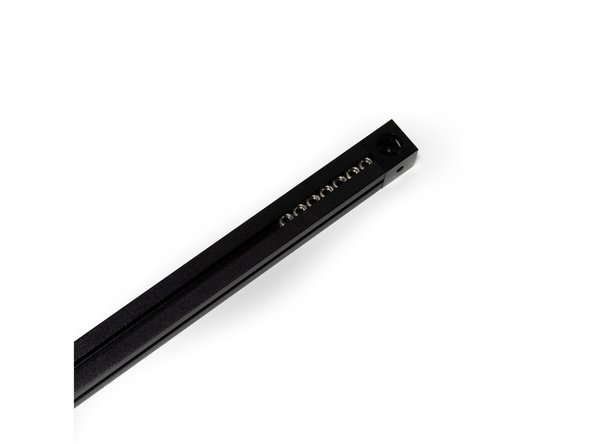
Slide (7) M3 nuts into the top channel.
-
Slide (4) M3 nuts into the top channel.
-
Note on the corner cube, the small hole is pointing to the right in this image.
-
-
-
Attach Second Corner Cube to Top Left Extrusion using (1) M3 x 8mm socket cap head screw. Be sure the large hole is up, small hole is down.
-
Note on both corner cubes, the small hole is pointing to the right in this image
-
-
-
Attach the (2) 245mm Top Front and Top Back Extrusions using (1) M3 x 8mm socket cap head screw each.
-
-
-
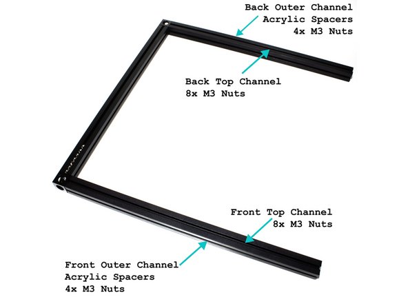
(8) M3 nuts go in the top channel of the back extrusion.
-
(8) M3 nuts go in the front channel of the front extrusion.
-
Insert the acrylic spacer inserts and M3 nuts in the top outer channel. There should be 2x 5mm spacers, 3x 81mm spacers, and 4 M3 nuts (See second image for reference).
-
Insert the acrylic spacer inserts and M3 nuts in the front outer channel. There should be 2x 5mm spacers, 3x 81mm spacers, and 4 M3 nuts (See second image for reference).
-