-
-
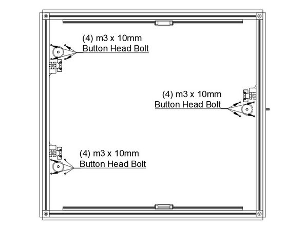
Install the (3) 1.8 degree Z steppers into the bottom panel using (4) M3 x 10mm button head bolts per stepper. The connectors should point towards the right side of the printer.
-
It's important the Z towers are positioned on the correct side of the steppers, as is shown in the picture.
-
-
-
Skip this step if using an aluminum base plate
-
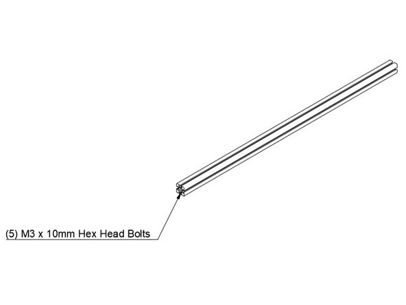
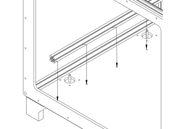
Insert (5) M3 x 10mm Hex Head Bolts into the bottom channel of one of the remaining 425mm Extrusions.
-
Lower the extrusion to the bottom panel so the bolts go through the 5 holes that go front to back in the panel, near the left side steppers.
-
Secure the bottom panel brace using (5) M3 washers and (5) M3 nuts on the bottom side of the printer.
-
Repeat this process for the brace on the right side of the bottom panel.
-
-
-
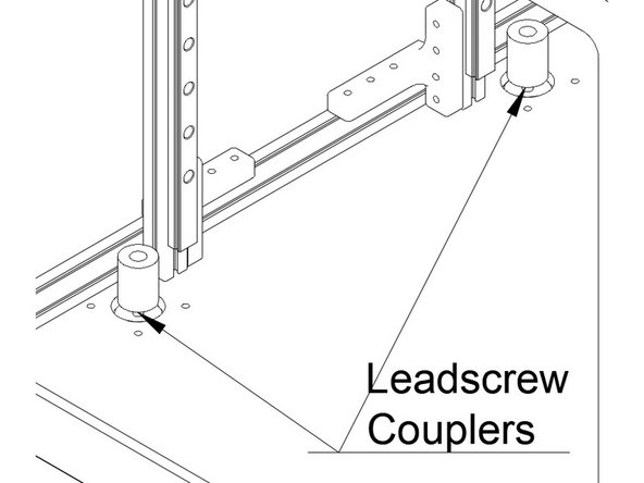
Install the (3) Leadscrew couplers onto the Z stepper shafts. The couplers should be fully seated and tightened.
-
The Couplers are silver, with colored plastic combining the two halves.
-
The third stepper on the right side of the printer is not pictured.
-
-
-
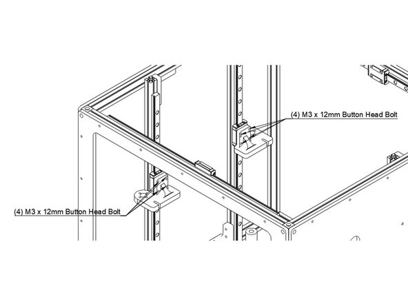
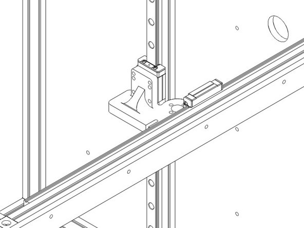
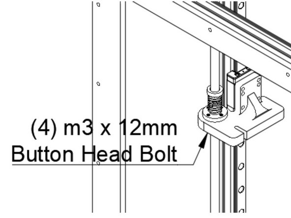
Install the (3) Z Yokes onto the Z carriages using (4) M3 x 12mm Button Head Bolts each. Note the orientation of the yokes in the pictures - ensure the hole for the leadscrew lines up over the stepper.
-
For Misumi linear rails, use M3 x 10mm instead of M3 x 12mm bolts.
-
-
-
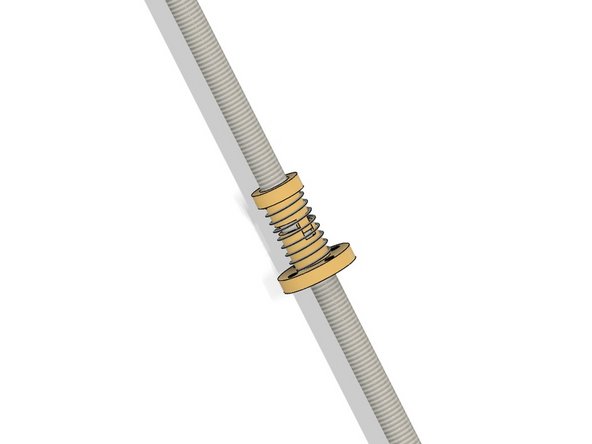
Prepare the anti-backlash nut for mounting onto the leadscrew.
-
Thread the bottom half (with the flange) down onto the screw until just the teeth are sticking up past the end of the leadscrew.
-
Put the spring on the bottom of the leadscrew nut and hold it there until the next step.
-
Insert the top of the leadscrew nut, pushing down until the teeth in the upper and lower parts interlock.
-
Thread the nut assembly onto the leadscrew, until it's about 1/3 of the way down.
-
Repeat the above steps for the other (2) leadscrews.
-
-
-
Insert the leadscrew down through the hole in the yoke, and into the leadscrew coupler.
-
You may need to slide the Z tower around to line it up so you can get the leadscrew into the coupler.
-
Tighten the grub screw in the coupler.
-
Insert (4) M3 x 12mm Button head bolts through the bottom of the yokes, and into the holes on the leadscrew nut flange. Do not overtighten, you can strip the Delrin.
-