Difficulty
Moderate
Steps
10
Time Required
- D) Bottom Extrusions Assembly 10 steps

In Progress
This guide is currently being written. Reload periodically to see the latest changes.
Quiz
0
Introduction
It's assumed that you're building a kit from Filastruder, and you've completed all previous sections. At the end of this section you should have a "bottom extrusions" assembly together for your RailCore frame.
-
-
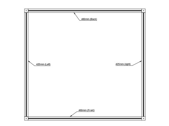
Layout Bottom Frame as shown. Note that the corner cubes should have a small hole facing up.
-
It is a good idea to mark each extrusion with a bit of masking tape on top, indicating which extrusion it is.
-
-
-
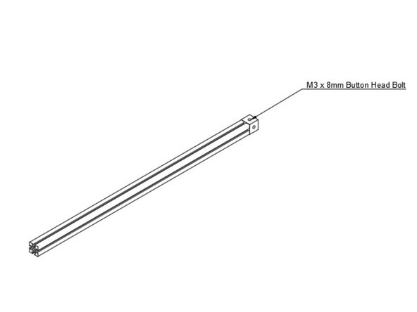
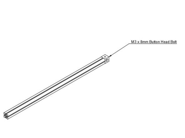
Use (1) m3 x 8mm Button head bolt to the bottom left extrusion. Note the orientation of the corner cube.
-
-
-
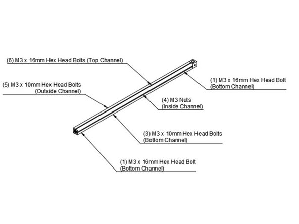
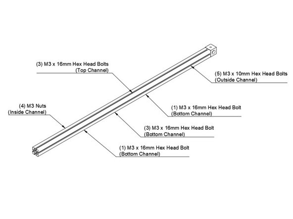
Slide (6) m3 x 16mm hex head bolts into the top channel.
-
Slide (5) m3 x 10mm hex head bolts into the outside channel.
-
Slide (4) m3 nuts into the inside channel.
-
In the bottom channel the order is (1) m3 x 16mm head head bolt, (3) m3 x 10mm hex head bolts, (1) m3 x 16mm hex head bolts. It is very important they're in this order, the longer bolts on the end are for attaching the feet.
-
-
-
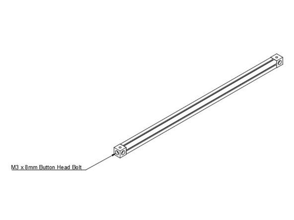
Use (1) m3 x 8mm Button Head bolt to attach the second corner cube to the other end of the bottom left extrusion.
-
-
-
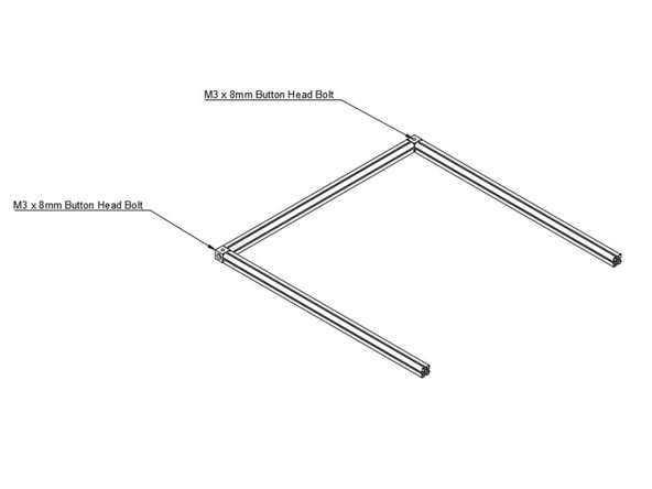
Attach Bottom Front and Bottom Back Extrusions using (1) M3 x 8mm Button Head Bolt each.
-
-
-
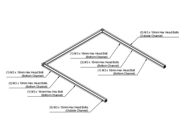
Slide (5) m3 x 10mm hex head bolts in the outside channel of the bottom rear extrusion.
-
The bottom channel of the bottom rear extrusion gets (1)m3 x 16mm hex head bolt, (3) m3 x 10mm hex head bolts, and (1) m3 x 16mm hex head bolt, in that order.
-
Slide (5) m3 x 10mm hex head bolts in the outside channel of the bottom front extrusion.
-
The bottom channel of the bottom front extrusion gets (1)m3 x 16mm hex head bolt, (3) m3 x 10mm hex head bolts, and (1) m3 x 16mm hex head bolt, in that order.
-
Set this assembly aside, so you can assemble the bottom right extrusion.
-
-
-
Use (1) m3 x 8mm button head bolt to add a corner cube to the bottom right extrusion. Note the orientation of the corner cube, a small hole needs to face up.
-
-
-
Slide (3) m3 x 16mm hex head bolts in the top channel
-
Slide (4) m3 nuts in the inside channel.
-
Slide (5) m3 x 10mm hex head bolts in the outside channel.
-
In the bottom channel add the following hardware in this order. (1) m3 x 16mm hex head Bolt. (3) m3 x 10mm hex head bolts. (1) m3 x 10mm hex head bolt.
-
-
-
Add Second Corner Cube to Bottom Right Extrusion
-
-
-
Attach Bottom Right Extrusion to the Rest of the Bottom Frame
-